Web the block diagram of switching power supply circuit arrangement is as follows: The input and output of the circuit include the rectifier and filter circuit. A feedback mechanism (usually done via.
How Does a Switching Power Supply Work 1 (schematic, explanation
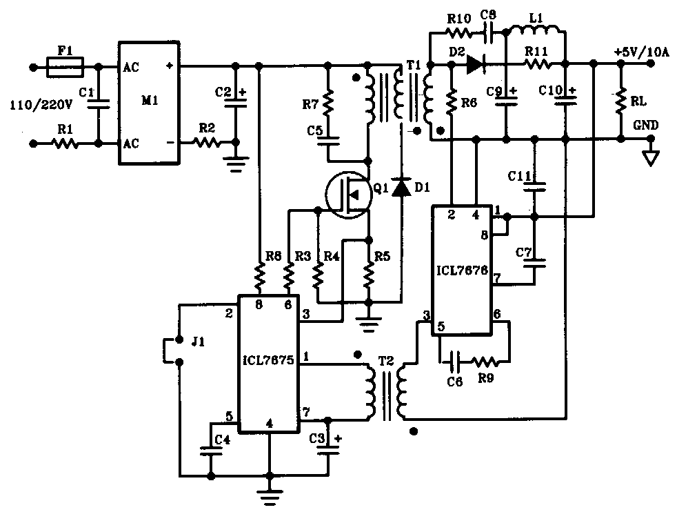
The transistor q1 will serves as the on/off switch circuit, we control them by lighting connection.
Web The Guide To Smps Switching Power Supply For Both Designers And Buyers.
Switch mode power supplies offer the advantages of smaller size, weight, and cost while achieving much higher power efficiencies. It is not used to give a detailed look at the system. Web basic working figure 1 is shown the simple circuit of this switching power supply.
Web It Is Quite Easy To Understand The Working Process Of The Switching Power Supply.
The majority of electronic dc loads are supplied from standard power sources. I also explain how you could modify a switching power supply output. Web schematic capture and circuit simulation signal/power integrity toggle submenu for:
The Output Rectifier Converts The High Frequency Ac Output To Dc.
The basic switching converter consists of a power switching stage and a control circuit. Web episode 772 let's look at a switch mode power supply. Web after you have an understanding of the basic definition of switching power supply, you may be willing to further explore its application and deepen your understanding.
Web In This Tutorial, We Will Learn How To Build A 12V Smps Circuit That Would Convert Ac Mains Power To 12V Dc With A Maximum Current Rating Of 1.25A.
Complete with schematics and detailed instructions. Web the schematic in my db of reverse engineered schematics: Then look at the design.
It Features A Pwm Controller That Turns The Voltage On And Off To Provide The Required Voltage Level.
Almost any product can benefit from a reduction in weight and size. Switch mode power supplies have a more complex circuit design than linear Web a switched power supply is an electronic power supply that converts electric power efficiently.
They Work By Feeding A Dc Voltage (Rectified From Ac First, Where Needed), To A Ferrite High Frequency Transformer Via A Controlled Oscillator.
Fig.1 block diagram of switching power supply circuit arrangement dtetails & analyses ⅱ the principle of the input circuit and the common circuits 2.1 principle of ac input rectifier filter circuit fig.2 the schematic of input filter circuit This controller circuit will control the q1 to on/off circuit by the frequency 20khz. Web block diagram of a switching power supply.
A Basic Introduction To Switching Supplies.
Only the most significant and important parts of a system will be shown in the schematic; Because the various electronic projects need to use them as an energy source. Web forward every new electronic product, except those that are battery powered, requires converting off−line 115 vac or 230 vac power to some dc voltage for powering the electronics.
Figure 1 The Basic Of Dc Switching Power Supply
These listings below may help you choose the type to match your usage, also most of them are cheap and easy to build. Web learn the benefits of switch mode power supplies, how they work, and how to build them. Web why switch mode power supplies?
Web You Are Looking For Many Power Supply Circuit Diagrams, Right?
Web a power supply is an electrical device that converts the electric current that comes from a power source to the voltage value necessary for powering a load, like a motor or an electronic device. A switching power supply is commonly used in electronics. Find power supply by spec.
The Pwm Switching Power Supply, Unlike A Linear Power Supply, Allows The Power Transistor To Flip Between On And Off States.
Web here is an example of an electronic schematic diagram. Therefore, in this blog, we will introduce 6 simple switching power supply circuit design schematics to you. Reverse engineer and draw schematic.
There Are Two Main Designs For Power Supplies:
Web by definition, a switch mode power supply (smps) is a type of power supply that uses semiconductor switching techniques, rather than standard linear methods to provide the required output voltage. A linear power supply and a switching power supply. Web i show a smps from a dvd player as an example, i draw a schematic of it and i explain how does it work using this example.
In A Linear Power Supply, The Power Transistor Is Operating In A Linear Mode.
The highlight of this circuit is that it works at a high frequency.