Web circuit diagram with all the components assembled on the breadboard is shown below so that even if a person doesn’t know much about circuit analysis he/she should be able to do the connections accurately : 0 70 1 minute read. In this circuit, we are operating 555 timer ic in bistable mode.
The Simple Panic Alarm Circuit 555 Timer Projects
This triggers t1.when t1 conducts, the trigger pin of the monostable timer ic2 will be grounded and the timer triggers.
Web Here Panic Button Alarm Circuit Will Designed Using 555 Timer Icky In Astable Mode.
It is made to be working reliably as it has simple to use and not so sensitive hardware like 555 timer, ceramic buzzer, capacitors, etc. In our case we need two stable states. For complete project with circuit diagram, visit:
It Helps Us To Intimate Others About Magnitude Bad Situation Without Any Delay.
Web in this tutorial, we will show you how to make a panic/emergency alarm circuit using some of the basic electronic components. Web panic alarm lab notes. Web demonstration video of panic alarm circuit using 555 timer ic.
Web This Panic Button Emergency Electric Is Conceived Using 555 Timer Ic In Astable Mode.
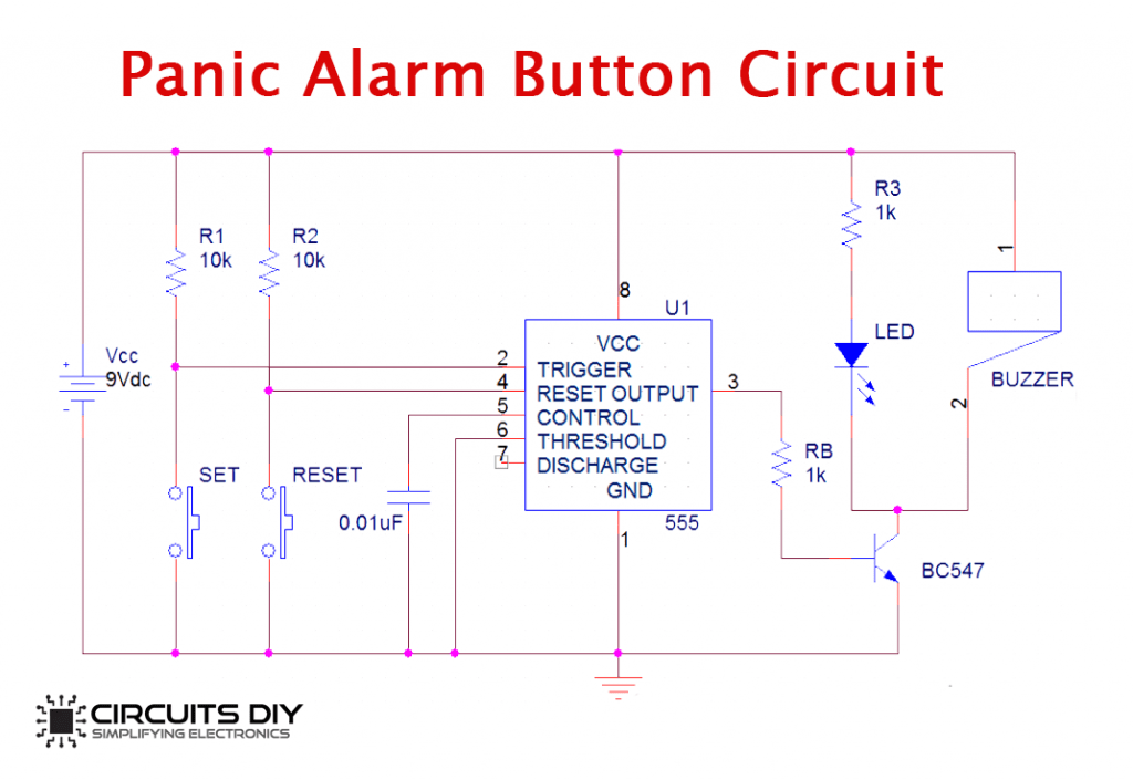
Web below is the circuit diagram of the panic alarm button using 555 ic, configuration selection: This circuit is made with a low cost hardware using ic 555 timer, buzzer, a few resistors and capacitors. Connect 10k resistors from vcc to pushbuttons.
The Touch Plate Fixed On The Wall Near The Bedside Gives An Easy Access To The Person On Bed Rest So That He May Call For Assistance Without Much Difficulty.
It helps us to intimate select about our bad situation without any delayed. Resistors are the passive device with two terminals. It is made to be working reliably as it has simple to use and not so sensitive hardware like 555 timer, ceramic buzzer, capacitors, etc.
Web A Panic Alarm Circuit Is Used To Send An Emergency Signal Immediately To The People In A Nearby Location To Call For Help Or To Alert Them.
In this project, i will show how to design and build a simple panic alarm circuit using 555 timer ic and a few other easily available components. Sketch created,compiled & uploaded (to arduino board) using arduino ide0022. As we have assembled the hardware we should feel safe and secure now.
Web Panic Alarm Circuit Diagram:
Web panic alarm circuit diagram when the mic detects clap sound, the ac signals pass through c1and ic1 amplifies the signal. If you feel threatened or need emergency assistance, simply activate this alert.it will attract the attention of others for immediate help.the alarm will go on for three minutes and then stop.it's especially suitable for women traveling alone and it's small enough to fit in a. This circuit can be used to activate an alarm in case of any emergencies.
The Time For Water Supply Is Determined By Administration… Read More »
Use standard flexible wires for interconnection between two boards. The possible panic situation can be any, it is not restricted to a few situations. This circuit can be used to send an emergency signal immediately to people in a nearby.
This Circuit Is Made With A Low Cost Hardware Using Ic 555 Timer, Buzzer, A Few Resistors And Capacitors.
Web panic alarm circuit diagram: Outline toggle panic alarm circuit diagram components required introduction Web a panic alarm button circuit is used to send an emergency signal immediately to the people in nearby location to call for help or to alert them
The Jal State Board Supplies Water For A Limited Duration In A Day.
Place the 555 timer ic and push switches on the breadboard. Web this is the circuit diagram of drinking water alarm based a small water sensor by using aluminium foil and plastic foil, and connected to a very simple alarm based a 555 ic timer. This circuit can be used to activate an alarm in case of any emergencies.
There Are Three Popular Configurations Of 555 Timer Ic, Astable Multivibrator Monostable Multivibrator Bistable Multivibrator They Differ By The Number Of Stable States In The Circuit.
Basically, it is a transistorised timer using the charging/discharging property of a capacitor. Web simple panic alarm circuit hardware components. Web expert engineer january 8, 2022.
Web Circuit Diagram Of Burgler Alarm.
This is a simple circuit named panic alarm which helps in intimating others regarding our bad situation without any delay. She helps us to indoor others about our bad situation without either delay. This circuit is made with a low cost hardware using ic 555 timer, buzzer, a few resistors and capacitors.