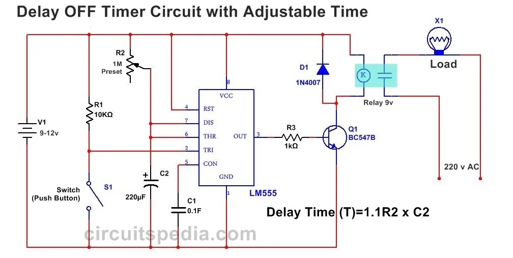
Web the timer component c of off delay timer wiring diagrams is the key element in this system. The delay can be adjusted to suit the needs of the user. A delay timer off is such a circuit through which your connected device automatically gets off after some time of turning on it.
555 Delay OFF Timer Circuit For Delay Before Turn OFF Circuit
The plc off delay timer can be used when you want to wait until.
555 Delay Off Timer Circuit For Before Turn.
The word itself you may come to know, that “on delay = delayed on”. This type of component is invaluable in automation systems, where there is a need for precise timing. Time delay relay circuit with 555.
Saya Menggunkan Rangkaian Ini Untuk Membuat Mesin Pemberi Makan.
This feature can be used in ladder diagrams, process sequences, and other control systems. Dua transistor yang digunakan adalah bc548. Use cu wire of 75 dec.
D1 Adalah Diode Zener 3,3V Dan D2 Adalah 1N4002.
Web diposting oleh admin may 25, 2021. Ini adalah rangkaian delay off timer dengan dua transistor yang dapat diaplikasikan untuk membuat mesin pemberi makan ikan otomatis. The controlling unit, the timer, and the wiring assembly.
Web Structure Off Delay Timer Circuit Diagram Off Delay Timer Circuit Diagram By Gracia Grace | January 13, 2023 0 Comment When It Comes To Modern Engineering, Off Delay Timers Are An Essential Component Of Many Circuits.
Web what is the delay timer off circuit? Time delay circuit using triac and 555 timer electronics area. Web when it comes to wiring your schneider off delay timer, it’s important to start off with the right diagram.
555 Delay Timer With On Off Basic Project.
Thankfully, most manufacturers provide detailed diagrams to make the wiring process easier. Web this guide will explain everything you need to know about off delay timer relay wiring diagrams. It helps assign certain intervals to turn on and off the power source.
Web An Off Delay Timer Relay Is An Electrical Component That Is Used To Create A Delay Between When A Signal Is Sent And When A Response Is Received.
How does an off delay timer relay. Web this diagram typically consists of two main sections: Learn on delay timer wiring :.
On Delay, Timers Are The Most Used Timer In Electric Circuit.
Time delay relay circuit using 555 timer ic electronics projects. Web 12rdt4 gic analogue timer micon 175 off delay. Time delay relay circuit using 555 timer ic electronics projects.
Each Section Has Further Subsections That Provide More Detailed Information About The Components And Connections Involved.
Geya delay timer switch ac dc 12v 240v mini power on time relay din rail type grt8 a1. Web wiring an off delay control circuit timer with magnetic contactor and h3y relay. Off delay timer relays are used to control systems that require short bursts of power.
Web Nand Gate Timer Circuit Delay Off.
It’s important to note that there are two main wiring diagrams for these types of timers—one for ac and one for dc. These relays work by keeping a circuit closed until a. Web the plc off delay timer allows us to set a delay time for the start of an event, which is then programmed into the plc.
Web 9.09K Subscribers Subscribe 6.2K Views 1 Year Ago In This Video You Will Learn About , Off Delay Timer Wiring With Bulb And Switch.
Web when it comes time to wire up a dayton off delay timer, the wiring diagram is key. On delay timer circuit diagram with relay using capacitor. The most common use case for this feature is in ladder diagrams.
How To Read The Electrical Wiring Diagram On Delay Timer:
How to connect sensor with off delay timer is also shown. It means the timer does not give the contact changeover until the preset time reached. Web the power off delay timer circuit diagram is a key factor when it comes to safety in many applications.
Off Delay Timer & Sensor Circuit Diagram Is Also Given.
Solid state timer relay electrical academia. These timed contacts are in series with motor starter m2. Web off delay timer connection | off delay timer wiring diagramif you're ever wondering how an off delay timer works, or where to find a wiring diagram for an of.
This Will Ensure That Your Connections Are Properly Done And That The Timer Operates Safely And Efficiently.
This circuit diagram is designed to provide a short delay before the power supply is cut off, enabling the system to shut down in an orderly manner and preventing any data loss. The left side, which is usually labeled “components” and the right side, which is usually labeled “connections”. Step by step explaination with diagram.thank you for your time guys.
Each Diagram Shows How To Connect The Timer’s Terminal Blocks, As Well As How To Wire The Outlets And Components.
Web off delay timer wiring connection with proximity switch/sensor and ac load load.


